How to implement a vector brush
Since I’ve previously written about how to implement a basic bitmap brush I thought it would be fun to figure out how to build a vector brush, like what you would find in Adobe Illustrator or Fireworks. A vector brush works the same as a bitmap brush from the viewpoint of the user, except that the resulting brushing stroke is scalable and otherwise editable after it is made. That’s because the resulting brush stroke ends up being a bezier path. In this post, I’ll show how it’s done.
If you’re impatient, you can always skip to the source code. It is licensed under the MIT license.
Naive Implementation
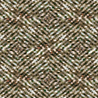
The direct way to implement the vector brush would be to simply record the mouse movements into a NSBezierPath. On a mouse down, create an NSBezierPath, do a move to the first point, then on subsequent mouse drags add line to’s to the NSBezierPath. Since I already have an NSBezierPath now, I can just draw it to represent the brush stroke. If you run the sample application with all the options under the Options menu (Show Points, Simplify Path, and Fit Curve) turned off, it’ll do exactly that. A brush stroke will look something like:

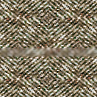
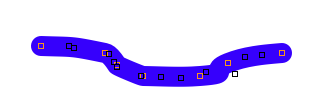
That actually doesn’t look bad. Does that mean I’m done? To answer myself, I’ll turn on the Show Points option under the Options menu:

Show Points draws an orange, hollow square around each of the points that make up the path. As you can see, there are a ton of them, about 160 in this case. Having that many points means editing the path afterwards is going to be rather difficult. Also, I can see that most of the points are redundant; they aren’t adding any new information to the path.
Brush strokes, simplified
At this point the best way to improve the my brush is to remove all the redundant points from our NSBezierPath. Since all the extra points don’t get in my way until mouse up happens, I’ll simply do some post processing on the NSBezierPath on mouse up. I’ll use the Ramer-Douglas-Peucker algorithm to identify and remove the redundant points. To demonstrate the effects of this algorithm, I’ll turn on the Simplify Path option, and draw another brush stroke:
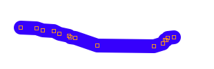
You can see a big difference here in the number of points required to make up the path. The sample application outputs (using NSLog) how many points the path had before and after simplifying the path. In this case, the points went down from 170 to 15.
The Idea
The idea behind the Ramer-Douglas-Peucker algorithm is pretty simple. It takes a path and a threshold as parameters. I’ll show an example to demonstrate it. Let’s start with the following path:
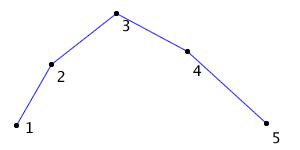
I’ve numbered the points for easy reference. To start with I imagine a line between the end points, 1 and 5. I then measure the distance between each of the interior points (2, 3, 5) and the line made by points 1 and 5.
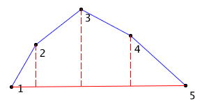
I take the greatest distance (the one between point 3 and my line) and compare it to the threshold passed in. If the distance exceeds the threshold, I have to subdivide the path and recurse. I split the path at the greatest distance (point 3 in this case), which gives me two paths: [1, 2, 3] and [3, 4, 5].
I repeat the process on [1, 2, 3] as my path:
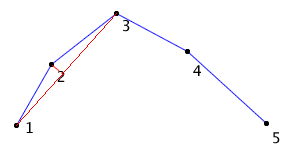
Here my end points are 1 and 3, and my only interior point is 2. Like before I take the distance between point 2 and the line formed by 1 and 3, and compare it to the threshold passed in. In this case, the distance is less than threshold. Thus, I can say the interior points are all redundant and the path [1, 2, 3] can be represented by the endpoints 1 and 3.
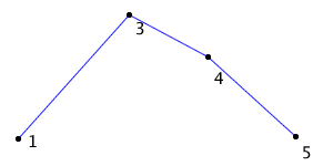
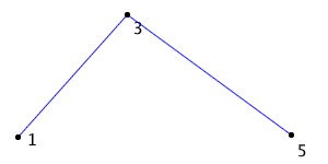
Going back to the second recursion mentioned, I repeat the same process on [3, 4, 5]. In this case the distance between point 4 and the line between points 3 and 5 is less than the threshold. Because of that, I can represent the path [3, 4, 5] with just the end points 3 and 5. Thus, the final result is:
The Code
As you might expect the code for this algorithm is rather simple. It’s just one method (not counting the utility methods to access NSBezierPath data), which I’ve added as a category to NSBezierPath.
It takes a threshold as a parameter and returns the simplified path. It needs at least three points on the path before the algorithm will work.
- (NSBezierPath *) fb_simplify:(CGFloat)threshold
{
    if ( [self elementCount] <= 2 )
        return self;
Next it calculates the distance between the interior points and the line formed by the two end points. It remembers the largest distance and where in the path that point is.
    CGFloat maximumDistance = 0.0;
    NSUInteger maximumIndex = 0;

    // Find the point the furtherest away
    for (NSUInteger i = 1; i < ([self elementCount] - 1); i++) {
        CGFloat distance = FBDistancePointToLine([self fb_pointAtIndex:i], [self fb_pointAtIndex:0], [self fb_pointAtIndex:[self elementCount] - 1]);
        if ( distance > maximumDistance ) {
            maximumDistance = distance;
            maximumIndex = i;
        }
    }
FBDistancePointToLine() is a function I wrote that calculates the distance between a point and a line. fb_pointAtIndex is just a helper method that returns the point on the path at that index.
Now that it has the greatest distance, it checks to see if that distance is significant. If it is, then it recurses on itself, passing in the two halves split by the greatest distance. When the recursive calls return it joins the two results back into one, and returns those.
    if ( maximumDistance >= threshold ) {
        // The distance is too great to simplify, so recurse
        NSBezierPath *results1 = [[self fb_subpathWithRange:NSMakeRange(0, maximumIndex + 1)] fb_simplify:threshold];
        NSBezierPath *results2 = [[self fb_subpathWithRange:NSMakeRange(maximumIndex, [self elementCount] - maximumIndex)] fb_simplify:threshold];

        [results1 fb_appendPath:[results2 fb_subpathWithRange:NSMakeRange(1, [results2 elementCount] - 1)]];
        return results1;
    }
fb_subpathWithRange: is another utility method. It makes a copy of part of the path specified, and returns it. fb_appendPath appends one path to another, except it also will remove spurious move to’s and replace them with line to’s.
Finally, if the greatest distance isn’t significant, then all the interior points are redundant. In this case, just create a new path with the two end points.
    NSBezierPath *path = [NSBezierPath bezierPath];
    [path fb_copyAttributesFrom:self];
    [path moveToPoint:[self fb_pointAtIndex:0]];
    [path lineToPoint:[self fb_pointAtIndex:[self elementCount] - 1]];
    return path;
}
The only new utility method this time is fb_copyAttributesFrom:, which copies over attributes like caps, joins, and miters to the target path.
Curvy is better
So now I have a much simplified path representing my brush stroke. But my path is comprised of lines only, which are quite limited in representing anything other than a line. I’d like to have a way to represent curves. That way editing the path afterward would be even more powerful, plus I could reduce the number of total points on my path even more. Enter bezier curves.
Defining bezier curves is beyond the scope of this article. As far as this post is concerned they are a parametric curve defined by four points: two end points and two control points.
To further improve my brush stroke, I’m going to take my simplified path of lines, and fit a series of bezier curves to it. The algorithm for doing this is documented in Graphics Gems 1 in the article titled “An Algorithm for Automatically Fitting Digitized Curves” by Philip J. Schneider. Unfortunately, Graphics Gems is out of print. A Kindle version is available on Amazon, but it is 1) US$80 and 2) a poor quality scan. I would suggest buying the book used if you want a copy.
You can see the results of curve fitting by turning on the Fit Curve options in the Options menu and drawing a stroke. Here’s an example:
The black boxes are bezier curve control points. In this case using both path simplification and curve fitting reduced the number points from 197 to 7. Even better, bezier curves give the user more flexibility and power when it comes to editing the path.
Curve fitting overview
The curve fitting technique is somewhat involved and makes use of several different algorithms. I’ll only cover the methods unique to the algorithm and skip over a lot of details. That said, the sample code is complete and commented, so it can be used to fill in the details.
To start with, I’ll assume the function Q(t) represents a bezier curve that fits the points on my path. The parameter, t, ranges from 0 to 1, and Q(t) outputs x,y coordinates on my bezier curve. The first thing to do is calculate estimated values of t that match up to the points on my path. That is, Q(t[index]) should equal the point on my path at index.
After generating inputs for Q(t), the next step is to try to fit one bezier curve to the all the points on the path given the inputs. (I’ll describe the exact process later.) I’ll then compute how far the resulting bezier curve falls from the points on my path. If the curve is close enough, then I’m done.
If the bezier curve isn’t close enough to fit, I’ll see if it’s close enough that it makes sense to refine the inputs (t). If it is, I’ll repeatedly refine the input parameters (t) using Newton’s Method, until the resulting bezier curve fits sufficiently or I try more than four times.
If refining the input parameters doesn’t lead to a fit, it’s time to give up on one bezier curve, divide the path, and recurse. I’ll split the path into two at the point the bezier curve is furtherest from (i.e. where the greatest error is at). I’ll then recurse on the two halves, and then combine the two resulting curves into one bezier path for the final result.
The method fb_fitCubicToRange: in the NSBezierPath (FitCurve) category contains the code for the process described above if you want more detail.
Fitting a bezier curve to points
Remember that a bezier curve is defined by four points, like below.
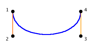
Here points 1 and 4 are the end points and 2 and 3 are the control points. The orange lines just visually connect the control point with its corresponding end point. The blue curve is the bezier itself.
If we’re given a path of points to fit a curve to:
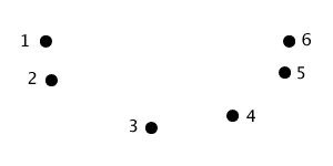
it’s easy to select the end points of the bezier curve; they’re simply the end points of the path (1 and 6 here). The direction of the control points relative to their end points is also simple to determine: simply compute the vector between the path end points and their nearest neighbor. In this case the direction of the left control point is the vector between points 1 and 2 in the path. The right control point direction is the vector between points 5 and 6. The only unknown in constructing our bezier curve is the distance between the control points and their respective end point.
Stated another way:
leftEndPoint = first point in path
rightEndPoint = last point in path
leftControlPoint = leftAlpha * leftTangent + leftEndPoint
rightControlPoint = rightAlpha * rightTangent + rightEndPoint
Where leftAlpha is the distance between the leftEndPoint and leftControlPoint, and rightAlpha is the distance between the rightEndPoint and the rightControlPoint. leftTangent and rightTangent are the unit vectors between the end points of the path and their closest neighbors.
By controlling the distance of the control points from their end points, I can affect the curve of the bezier. I want to chose distances (leftAlpha and rightAlpha) such that it best fits the points in the path. Formally stated, I want to minimize the squared errors as represented by:
S = SUM( (point[i] - Q(t[i])) ^ 2 )
Where point[i] is the point on the path at index i, t[i] is one of the estimated parameters I generated earlier, and Q is bezier curve. Remember that point[i] should be equal to Q(t[i]), assuming the bezier curve fits perfectly my points. Here I’m calculating how far each point on the bezier curve is off, squaring that, then adding it all up (squared errors). This is the error I calculate when I’m trying to determine if a bezier curve is close enough that I’m done. Right now though, I want to minimize S when calculating leftAlpha and rightAlpha.
Using the least squares approach I can write the equations I want to solve as:
d(S) / d(leftAlpha) = 0
d(S) / d(rightAlpha) = 0
Here d() is derivative, usually written as the Greek letter delta. S is the squared errors defined above.
At this point I do need to introduce the definition of a bezier curve:
Q(t) = SUM(V[i] * Bernstein[i](t))
Where i ranges between [0..3], and V is one of the points on the bezier curve. V[0] is the leftEndPoint, V[1] the leftControlPoint, V[2] the rightControlPoint, and V[3] the rightEndPoint. Berstein[i] is a polynomial that is highly regarded as boring for this discussion. (Look at the code if you really want to know.)
Now that I have Q defined, I can substitute it in the equation S, and then S into the two equations I want to solve. After a lot of mathematical voodoo and gymnastics (see the paper for all of that), I arrive at:
leftAlpha = det(X * C2) / det(C1 * C2)
rightAlpha = det(C1 * X) / det(C1 * C2)
Here det() is determinant, * is the dot product, and X, C1, and C2 are all 2×1 matrices defined below.
C1 = [SUM(A1[i] * A1[i]), SUM(A1[i] * A2[i])]
C2 = [SUM(A1[i] * A2[i]), SUM(A2[i] * A2[i])]
X = [SUM(partOfX * A1[i]), SUM(partOfX * A2[i])]
Where
partOfX = (points[i] - (leftEndPoint * Bernstein0(t[i]) + leftEndPoint * Bernstein1(t[i]) + rightEndPoint * Bernstein2(t[i]) + rightEndPoint * Bernstein3(t[i])))
And
A1[i] = leftTangent * Bernstein1(t[i])
A2[i] = rightTangent * Bernstein2(t[i])
If you’re interested in how this all plays out in code, check out the method fb_fitBezierInRange: in the NSBezierPath (FitCurve) category.
Calculating parameters (i.e. t)
The parameters (t) are useful for correlating the points on my path with the bezier curve I’m trying to fit. I know that t has to range from 0 to 1, and Q(t) is supposed to correspond to the points on my path. Q(0) should be the first point on my path, and Q(1) should be the last.
The initial estimate of t uses the chord length method. Ideally, t would be the length of curve from the left end point to the point corresponding to t, divided by the total length of the curve. However, the chord length method makes the assumption that a straight line is a reasonable estimate of a curve. So to estimate t, I measure the length of the line segments from the left end point to the point corresponding to t, then divide that by the length of all the line segments.
You can inspect the implementation of this in the fb_estimateParametersUsingChordLengthMethodInRange: method.
If my initial estimate proves to be poor, I can further refine it using Newton’s Method. Newton’s Method says I can refine each t value by:
t = t - f(t) / f'(t)
In my case
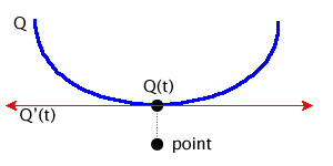
f(t) = (Q(t) - point) * Q'(t) = 0
Here (Q(t) –point) is the vector from a point on the bezier curve to the corresponding point on my path. Q’(t) is the first derivative, which is tangent to the bezier curve, Q, at t. (Q(t) –point) is orthogonal to Q’(t), which means the dot product of the two is zero.
Based on that, f’(t) is
f'(t) = (Q(t) - point) * Q''(t) + Q'(t) * Q'(t)
The NewtonsMethod() function in NSBezierPath+FitCurve.m implements this.
Conclusion
Although I skipped over a lot of detail when it came to curve fitting, hopefully this post has been helpful in understanding how it works, in addition to explaining the vector brush. For the details that I skipped over, the code should fill in the blanks. The vector brush is a fun tool to play with and the curve fitting algorithm has other applications too.